Problem
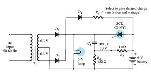
Refer to the emergency-lighting system of Fig.
a. Sketch the waveform of the full-wave rectified signal across the bulb using a drop of 0.7 V during conduction of each diode.
b. Determine the peak voltage across the capacitor C1 when the SCR1 is off.
c. What is the peak voltage across R1 during the charging phase if the battery voltage drops to 5 V?
d. What is the voltage across the lamp when the SCR turns on and the battery is fully charged at 6 V?
e. What is the current drawn from the battery if the lamp is dissipating 2 W of power?
FIG. Single-source emergency-lighting system.

Step-by-step solution
Step 1 of 7
Refer figure 17.14 in textbook for single-source emergency-lighting system.
(a)
Write the expression for peal voltage across the transformer secondary coil as follows:

Here,
Maximum voltage across the transformer secondary coil is

Substitute
 for
for  to calculate
  as follows:
Comment Step 2 of 7
For
 lamp, the potential across its terminals will be the resultant of the transformer peak voltage and diode pinch-off voltage.
Here,
The pinch-off voltage
 of diode
  is
is  .
.Substitute
 for
for  , and
, and  for
for  to calculate
  .
.
Hence, the potential across lamp terminal is
 .
.Thus the sketch of the full-wave rectified signal across the bulb is shown in Figure 1.

Figure 1
Comment Step 3 of 7
(b)
The potential drop across capacitor will be equal to mathematical resultant of the potential across the resistor
 and potential across lamp terminal
  , when the SCR is in off condition.
 …… (1)
Apply voltage divider rule across the network as follows:

Substitute
 for
for  , and
, and  for
for  , and
, and  for
for  to calculate
  .
.
Substitute
 for
for  , and
, and  for
for  to calculate
  as follows:
Comment Step 4 of 7
Hence, the potential drop across capacitor is
 .
.Comment Step 5 of 7
(c)
Apply Kirchhoff’s voltage law at the outer network as follows:

Substitute
 for
for  ,
,  for
for  , and
, and  for
for  to calculate
  as follows:
Hence, the potential drop across resistance
 is
is  .
.Comment Step 6 of 7
(d)When the SCR is in ON condition, the circuit is bypassed through SCR. There will be no current flow through resistor-capacitor circuit. The potential across the battery will be equal to the potential across the lamp terminals.

Substitute
 for
for  to calculate
  .
.
Hence, the potential drop across lamp is
 .
.Comment Step 7 of 7
(e)
Write the expression for power dissipated across the battery terminal.

Rewrite above expression for the current generated by the battery.

Substitute
 for
for  , and
, and  for
for  to calculate
  .
.
Hence, the current drawn from the battery is
 .
.Comment
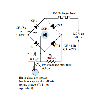
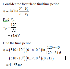
If the gate-firing potential is 40 V, what is the time period between successive triggering of the SCR?

