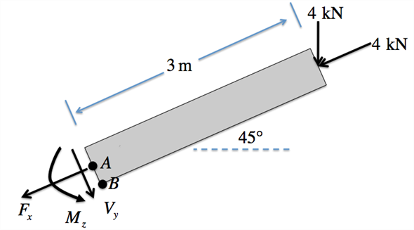
Draw the free body diagram of the beam as follow:
Apply force equilibrium condition along axial direction.
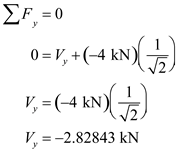
Apply force equilibrium condition along vertical direction.
Apply moment equilibrium condition about node A.
Apply the equation for moment of inertia,

, for a hollow rectangle.
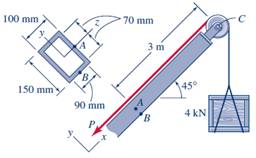
Here, the width of the outer rectangle is

, the height of the outer rectangle is

, the width of the inner rectangle is

, and the height of the inner rectangle is

,
Substitute 100 mm for

, 150 mm for

, 90 mm for

, and 140 mm for

.
Apply the equation for area,

, of the rectangle.
Substitute 100 mm for

, 150 mm for

, 90 mm for

, and 140 mm for

.
Apply the formula for static moment of area,

, at point

.
Substitute

for

,

for

,

for

, and

for

.
Apply the formula for shear stress at point A.
Substitute

for

,

for

,

for

, 90 mm for

, and 100 mm for

.
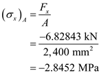
Apply the formula for the normal stress at point A.
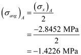
Apply the formula for the average normal stress at point A.
Substitute

for

.
Apply the formula for the radius of Mohr’s Circle for point A.
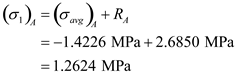
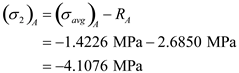
Apply the formula for the principle stresses at point A.

.
Substitute

for

and

for

to calculate the maximum and the minimum principal stresses at point

.
Therefore, the stresses at point

are

and

.
Apply the formula stresses at point B by using Equation 9.10.
Substitute

for

,

for

,

for

,

for

and

for

.
Point

lines on the bottom surface of the boom, so there is no shear stress.
Thus, the stresses at point

are

and

.
 Here, the width of the outer rectangle is
 Substitute 100 mm for
 Substitute
 Apply the formula for shear stress at point A.
 Substitute
 Therefore, the stresses at point
 Substitute
 Point
Point


 for
for  and
and  for
for .
.


 for
for  and
and  for
for .
.
